
|
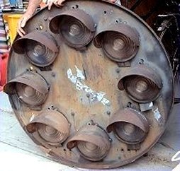
This is a complete (four-aspect) color-position light (CPL) signal head. Have you ever wondered what
was inside of one of those lamp units? Well, thanks to an old website that had the 1937 General Railway
Signal (GRS) Company catalog available, we can take a look under the hood (pun intended) of a GRS Type U lamp unit.
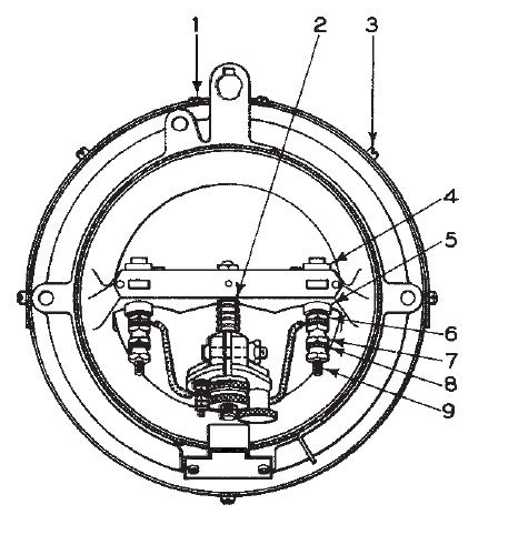
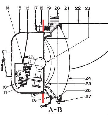
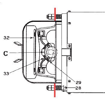
The diagrams and list of parts shown are from the catalog; the photographs are mine, taken of one of the lamp units from my CPL (shown in the lead photo), with the various prts numbered so that you can compare them to the drawings and see what they actually look like. |
|
|
||
|
|
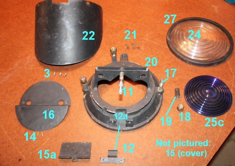
Screw, no. 10-32 x 3/16" fil. hd. for
fastening ring (27) to bezel ring (20) |
Screw, no. 6-32 x 5/16", with clip, for fastening lens (25) to light unit | ||
Spring for stud (11) |
Hood, for light unit |
||
Screw, no. 10-32 X 3/4"fil. hd. for
fastening hood (22) to bezel ring (20) |
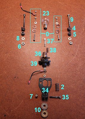
Incandescent bulb, 13.5 volt, 17 watts, for light unit |
||
Bushing for screw (9) |
Lens, outer doublet hot spot, 8-3/8", 4" focus |
||
Bushing for screw (9) |
Lens, inner doublet, 5-1/2" dia. green, for light unit |
||
Nut, no. 14-24 x 1/8", hex head, for terminal posts |
As above, except yellow |
||
Nut, no. 14-24 x 5/16", hex head, for terminal posts |
As above, except red |
||
Washer, for terminal posts |
As above, except lunar |
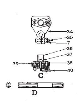
||
Screw, no. 14-24 x 2-7/16", sq. hd., used f-or terminal posts |
Gasket, for lenses (24 and 31) |
||
Adjusting nut, for light unit |
Bezel ring, as shown, for light unit |
||
Stud, for adjusting light unit | +
Pin, 3/32" x 3/4", for locking stud (17) to bezel ring |
||
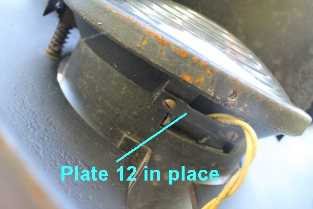
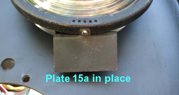
Plate, for closing opening in bottom of light unit |
Screw, no. 6-32 x 11/32" hex hd. with washer, for fastening sighting plate (33) to light unit |
||
Screw, no. 8-32 x 3/8" fil. hd., for fastening plate 912) to light unit |
Roundel complete, includes roundel clip and spring assembled together, for light units figs. B to B4 onlyB |
||
Screw, no. 6-32 x3/16", for fastening sighting strip (32) to shield (16) |
Lens, outer doublet 30° spredlite 8-3/8" dia., for light units figs. B to B4 only |
||
Cover, complete, includes clip and chain, for light unit |
Sighting strip, for light unit |
||
Shield, for light unit |
Adjustable sighting plate, for sighting light units |
||
Stud, 3/8"-16, for fastening light unit to background |
Bracket, for lamp receptacle |
||
Nut, 3/8"-16 x 3/8" hex, for stud (17) |
Screw, no. 14-24 x 1-3/8" sq. hd., for clamping bracket (34) to stud (11) |
||
Spring for stud (17) |
Receptacle, only, for lamp receptacle |
||
Bezel ring for light unit |
Plunger, for lamp receptacle |
||
Spring, for plunger (37) |
|||
Block, for receptacle |
|||
Adjusting nut, for receptacle |
|
|
|
|
 Back to Mike's B&O Signals Page
 Back to Mike's Railroad Page