
Two steps remain: wiring the CPL to function, and placing it in the yard. This section is about wiring it to function.
A little about relays
I am fortunate to have a friend, Abe, in New Cumberland, PA, who has amassed an incredible assortment of signal...um... parephenalia...over the 46 years he's worked for various railroads - Pennsy, Conrail, and now a shortline in Pennsylvania. He's provided me with five relays:
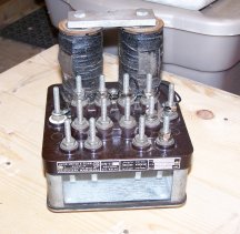
three US&S DN-11
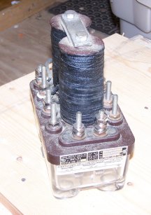
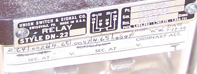
one US&S DN-22
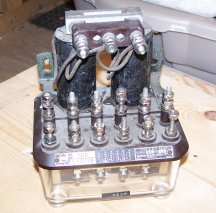
and one GRS Type K
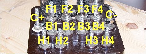
Below is a patent drawing, which happens to show a DN-11-type relay. Note the way the binding posts are connected to the relay contacts. The wire connecting the "heel" post and the heel contact is called the "heel ribbon"; also note that the terms front and back have absolutely no relation to the position of the contacts, which are up and down.
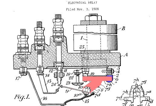
Note that the armature - shown in red - is up, indicating that he coil is energized; in this case, the "front" contact is energized; when the coil is de-energized the armature will drop away from the bottom of the coil and then the "back" contact will be energized. This concept is more easily demonstrated in the following drawing, also from a patent, showing the two positions of the armature; the red indicates the position of the armature when the coil is de-energized and the armature is "dropped out".
 Continued
 Back to Mike's Railroad Page