
|
General inormation regarding locomotive terminals
as copied from the book Maintenance of Way and Structures
by William Clyde Willard
First Edition, Second Impression © 1915 by the McGraw-Hill
Book Company, Inc.
|
|
as copied from the book Maintenance of Way and Structures
by William Clyde Willard
First Edition, Second Impression © 1915 by the McGraw-Hill
Book Company, Inc.
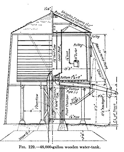
187. Water tanks. - Railway water tanks are usually built of wooden staves with iron
or steel hoops, though many tanks of large capacity are built of rivited steel plates, and a
few reinforced conrete tanks have been built. Wood is preferable for tanks of small
capacity and tanks used for temporary purposes. A wooden tank can be taken down and
re-erected with little difficulty in a new location. Th elife of wooden tanks depends
on the kind of lumber used, whether the tank is kept full, whegther the water is allowed to
freeze, painting of the outside, etc., and averages about 20 years. Th elife of the
hoopes is often only half that of the tank. The spacing of the hoops must be determined
by computing the water-pressure at all depths of the tank. The capacity varies from about
25,000 gal. to 100,000 gal., nut a few tanks with capacities exceding 500,000 gal. have been
built for railway purposes. Reinfoced-concrete water-tanks are an innovation in railway
service, though the first application of reinforced-concrete was a vessel for holding
water. The advantages to be gained by using reinforced-conrete for water-tanks are
durability and low maintenance cost. At present it appears that the advantages are
offset by the disadvantages, which are greater first cost, poor materials and workmanship,
difficulty of waterpfoofing the concrete, shrinakge and stretch of the concrete, unsightliness,
and effect of frost upon the saurated concrete. These tanks are either built as
standpipes or as elevated tanks on concrete columns or towers.
 Wooden water tank |
 Steel water tank |
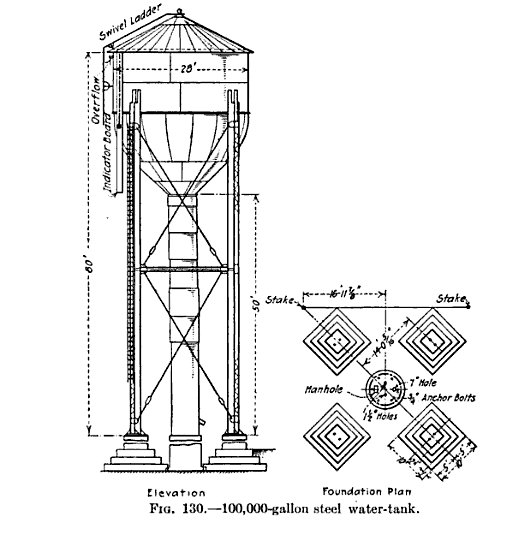
Water-tanks may be supplied by gravity; or by steam, gasoline, or electric pumps operated by the railway; or by municipal water supply. Steam power will be most economical when the pumping station is near a steam plant maintained for other purposes, such as shops, and when 100 lb. of coal is delivered to the pumping station is cheaper than 1 gal. of gasoline delivered at the gasoline storage tank. Where the reverse conditions obtain, gasoline will be the most economical. Electric power will be most economical if the pumping station is adjacent to a power line of the raileway, as in electrical territory or when alternating current is used for signal purposes. A 48,000 gal. wooden water tabk is shown in fig. 129, and a 100,000 gal. steel water-tank is shown in fig. 130
188. Water columns. - When it is unnecessary to to provude a storage supply, as
where the railway gets its water from an adequate municipal supply, or where it is
necessary for the railway to maintain a large tank or reservoir, a water column is more
economical than a water-tank. A water-column also the advantage that it can be located
here space is limited, as for instance between tracksand in such a position can serve two
tracks. A water-column consists of a vertical pipr with a horizontal spout at the top,
as shown in fig. 131.
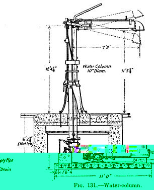
The valve gear is in a pit below ground at the base. A lever at the top of the column extends out over the track. When an engine is to take water, the fireman pulls down on the lever and through other connecting levers this opens the valve.
189. Track tanks. - In order to maintain long, fast passenger passenger runs it is
desirable for the engine to take water without stopping. Tracnk tanks were invented
for this purposes and in the past hae been used mostly in passenger servce. The serious
objections to stopping and statring heavy freight trains have brought about the adoption of
track-tanks also for freight service. A track tank is a shallow metal trough placed on
the ties between the rails. When an engine desires to take water from the tank a
scoop on the tender is lowered into the trough and the speed of the train elevates the water
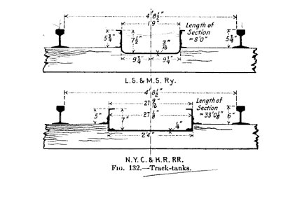
into the tender through an inclined pipe. The troughs are from 6 to 7½ deep and
from 19 to 29 in. wide, and usually dapped [let or imbedded ] into the tie. The
maximum dap should not exceed 2¼ in. The length of the tank depends on the
distance betwen tanks, the size of the tank, and the size and dip of the scoop. The
length is from 1200 to 2600 ft., averaging about 2000 ft. and the tanks should be about
40 miles apart. Track-tanks should be located on tangents, though they can be operated
on curves up to 3° - and at places where the train can have speeds of about 25 miles an
hour.
&nbsop;
The first track-tank appears to have been installed on the London & North Western Railway, of England, about 1857. The first track tank in America was intalled in 1870 by the New York Central.
Track-tanks introduce several unusual maintenance conditions requiring special attention. From 20 to 50 per cent. of the water is splashed out on the track and wasted, Elaborate drainage is necessary of this water before it reaches and softens the roadbed, or in the winter, before it freezes and heaces the track. Also some means must be taken in cold weather to prevent the water from freezing in the tanks. Drainage is accomplished by paving the top of the roadbed with large stones upon which a good depth of broken stone ballast is laced, by placing deep subdrains between the tracks, and by providing numerous cross drains to convey the water from the longitudinal drains to the side of the track. The New York Central installs surface box drains every 50 ft., longitudinal graded trenches filled with cobble stones between the tracks, and transverse tile subdrains intercepting the longitudinal drains every 100 ft. This method has proved satisfactory inquickly disposing of the water.
Two systems are used to heat the water in the winter. In modern installations, one or more water mains extend nearly the lentgth of the tank and water is supplies to the tank at several points from branch connections. The supply is controlled by automoatic valves actuated by a change in the level of the water.The number of inlets required depends on the interval between trains. QA trough 1400 ft. long and 27 in. wide requires the from 4 to 6 min. to fill from 3 inlets. In the direct-heating system steam-pipes run run the length of the troughs, and branch-pipes, at intevals of about 33 ft., discharge steam into the bottom or sides of the trough.
In the circulatory system the ends of several sections of pipe of about 4 in. diameter are connected to the trough. A circulation is maintained through the pipes, and the water is heated by injecting steam at the inlet to each section of the pipe. The sections of pipe are 333 feet long in recentinstallations of tanks 2000 ft. on the Lake Shore and Michigan Southern. The direct heating system appears to be the most economicalas it requires less pipe, there is little loss of heat, less heat is required. The majority of track-tanks used hitherto have been made of sections of metal troughs bolted together. The earlier tanks of this kind were made of cast iron, but sheet metal or sheet iron bent to the desired form, isnow generally used. The New York Cenreral has recently adopted a standard trough built up of two channels with flanges turned in which form the sides, and a plat plate riveted to the lower flange of each channel, which forms the bottom. This device has several advantages over the one-piece cross-section. The first cost is less, and the bottom, where the principal wear of a track-tank occurs, can be renwed separately. These two types of troughs are shown in fig. 132. An inclined plate from 7 to 10 f. long must be placed on each side of each end of the trough to lift the scoop if it is lowered to soon or not raised soon enough. At Whitmore, Pa., the Pennsylvania Railroad has a track-tank 2600 ft. long in each of the two east-bound tracks. 2,250,000 gal. f water are used in 24 hr. at this water station, which is probably the largest amount of water consumed at any railway water station in America.
190. Coaling Stations. - The railways of the United States consume about 120.000.000 tons of coal per year. The labor cost of placing the coal in the tender of a locomotive increases the final cost per ton to railway from 0.1 to 5 percent. One One cent saved per ton would mean a yearly saving of $1,200,000. The labor cost depends on the method used in operating the coaling station and varies considerably for different methods of handlingthe coal. In considering the type of coaling station to be used at any point several things must be considered: ground room, especially at busy terminals, is important; the first cost of the plant together with the relative expense of operating and maintaining it; the type of plant best suited for traffic conditions at that place; and the character of cars in which coal is received. The tendency is to adopt plants which cane be operated by a minimum number of men.
Coaling stations may be classified as follows: (1)Chutes. (2)Clam-shell buckets. (3)Mechanical. (4)Miscellaneous. There are an endless number of coaling stations in use with various modifications based entirely on local conditions. Where the amount of coal is small the coal is usually shoveled from the car directly to the tender or from he car to an elevated platform and then to the tender.
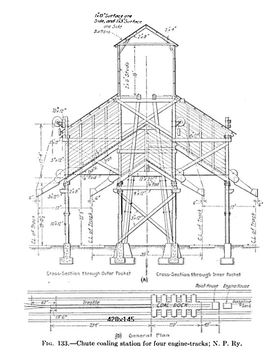
Coal-chutes usually consist of an inclined track leading to a level trestle from 12 to 45 or
50 fet above the ground, at the side of which bis are constructed. The entire structure
shouuld be covered with a roof. If the incline is not over 5 per cent, the cars can be
pushed up by a locomotive. If space is not available, a short, steep incline having
about a 20 per cent gradient can be used and the cars hauled up by a stationary engine and
cable. The coal is either shoveled from the car to the bin or, if dump cars are available
and the trestle is made higher, the coal can be dumped into the bins by gravity. When a
locomotve wishes to take coal a chute carries the coal from the bin to the tender If
ground is available the capacity of plant of this kind can be made to supply from one to
four engine-tracks. A chute coaling station, or "coaling dock", is shown in for supplying
four engine-tracks is shown in plan and elevation on figure 133. The approach trestle is
on a 20 per cent gradient. The cars are hauled up cable and the coal falls by gravity
into the bin. The tresetle has ten 12-ft, sections and has a capacity of 900 tons. After
the first 10 years the yearly cost of maintenance of wooden coaling stations is about 10 per
cent of the first cost.
Coal-trestles are used in coal storage yards, and frequently at coaling stations where locomotive cranes are used for coaling engines. The coal-cars are run up the trestle and the coal is dumped by gravity upon piles below.
Locomotive cranes and clam shell buckets are used on several large railways. They may be used to transfer the coal from the pile or car to an elevated bin from which the coal drops by gravity to the tender, or they may transfer the coal directly to the tender. Where the number of locomotives to coaled is not large this is an economical method of handling the coal. A plant of this kind requires considerable space, the coal being exposed to the weather and may deteiorate in vale, and and there is danger of spontaneous combustion.
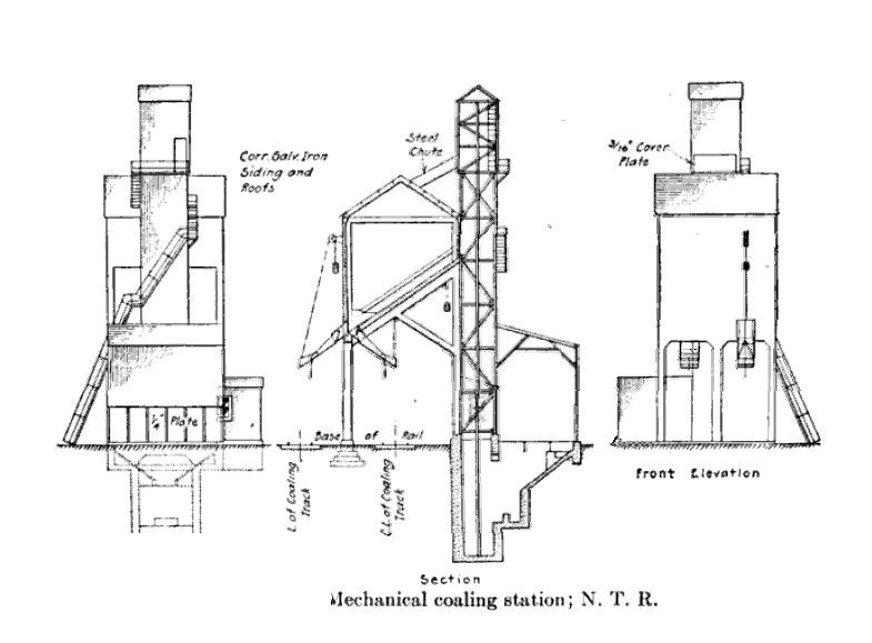
The general features of mechanical coaling stations are the dumping of coal from self-cleaning
cars into a pit, which in some plants contains a breaking device; elevating the coal from the
pit to the storage bin some distance above the track; weighing the coal%E59 and delivering
the coal from the bin, through a chute, to the locomotive.. It is desirable that the
weight of the coal given a locomotive be known accurately so that consumption per ton-mile
can be determined, but in the past this seldom has been done. The breaking device may
be a mechanical crusher, or bars against which the coal falls. The coal is then raised to
the bin by a continuous bucket elevator or by elevators. Mechanical coaling stations are
constructed of wood, metal or reinforced concrete. &nbs;A 200-ton capacity mechaical coaling
station with reinforced concrete coal-pocket built by National Transcontinental Railway is
show in Fig 134.
In general, where the amount of coal to be handled is from from 100 to 250 tons per day a derrick and bucket plant, a locomotive crane, or a clam-shell bucket and chute combined, are advisable. &nbps;When more than 250 tons per day are handled a trestle and chute or a mechanical plant are most economic. Every coaling station should have a storage capacity sufficient for several days'supply At many plants the coal must be stored in cars; otherwise additional handling of the coal is necessary. Both are uneconomical.
191. Sand for lomotives. - At engine terminals an adequate provision should be made for supplying dry san to locomotives. &nbs;Mechainal coaling stations usually include facilities for drying, elevating, storing and supplying sand to locomotives. The average locomotive sandbox holds from 6 to 10 cu. ft. of sand. The green sand is usually unloaded in piles or bins near the coaling station, the sand is dried in a sand-drying oven and the dry sand is placed in an elevated hopper from which it is drawn by gravity through a spout to the engine.
192. Ash pits. - The ash-pans of the average freight-train contain from 1 to 2 cu.
yd. of ashes at the end of the run. The design of the ash plant will depend on the
numer of engines handled per day, At a terminal hadling 100 enngines in 24 hr., from
100 to 200 cu. yd. of ashes must be handled. The most satisfactory ash-plant for
handling more than fifty engines per day consists of a pit with engine tracks on one or
bot sides. &nsp;One rail, or both rails,of the engine track is carried on metal piers over a
shallow pit called the shovelling platform. Outside the pier the pit is made from 2 to
8 ft. deeper to carry a depessed track. if proper drainage ofthe depressed track can be
secured an a large volume of ashes mut be handled, the pit-track should be depressed enough
to bring the tops of gondola cars slightly belowe the shovling platform. A few
improvised pits have been constructed so that the ashes slide by gravity or can be washed into
the ash cars.

The entire construction of the pit must be fireproof. Concrete is not satisfactory for the surfaces which come in contacvt with the hot ashes. Metal columns, fire-brick for the walls and floor of the shoveling platform, and concrete for the depressed track are satisfactory materials. The time required to clean the ashes of a small engine is from 10 to 15 min. A medium-sized engine requires about 30 min. and a large engine about 45 min. If the ashpans are frozen the time required may be several times longer. The pit may serve one or two engine tracks abd nay be made large enough to accomodate from one to three engines at a time on each track. Under normal conditions the labor cost of cleaning is from 18 to 30 cts. per engine and the cost of handling ashes is from 3 to 5 cts. per cubic yd. Figure 135 shows an ash-pit with depressed track and one engine track.
195. Turntables and wye tracks. - In 1895 the average length of locomotives was 65 ft.
In 20 years the length increased to about 85 ft. As the length increased the
strength increased corrrepondingy, but at present both length and strength have fallen
behind the increase in size of the largest locomotives now in service. Assuming the
strenght of the table to be suficient to carry the loads with more or less safety, length is
the most important feature of design. The length os determined by the length of
wheel base and the position of the center of gravity of the longest locomotive to be
turned. The table is turned easier if the loads of the arms are balanced. The
most unfavorable condition is an empty tender and a fulll boiler. If possible the
length of the table should be such as to balance the engine, even under these conditions.
This requires a minimum length equall to twice the distance from the center of gravity to the
rear tender wheel, If the engine is not balanced on the table the power required to
turn it is considerable and the table and its supports are subjected to severe stresses fow
which they were not designed. A 90 ft. table will balance most of the heavy freight- and
passenger-engines now in service, while a 100 ft. table will balance the medium sized Mallet. &nbs;p
The present standard length of American and Canadian railways is from 75 to 100 ft. Many
shorter tables will be found on old lines and a few longer tables have been built to handle
large Mallet engines.
Three types of types of turntables are used:)(a)through' (b)halg-through or through girder and (c) deck. Only a few through tables are being used and and the through-girder table is usually referred to as a through table. s;Economy in pit construction results from the use of a through-table, but a heavier table is required. The track usually is of the open-floor type, but steel-plate floors have been used in a few cases. Hand-powwer is ecomical for operating the table if only a few light engines must be turned. Electric power is most efficient.
Perhaps the most important part of a table is the center. Centers may be classified as conical roller beaings, disc bearibngs, and ball bearings, the numbers in use are in the order given. Roller centers turn easier than disc centers,
The hammering of the ends of a turntable from the wheels of entering engines is the most damaging feature in its operation. The shore rails are subjected to much the same shocks from leaving wheels, hence the circular rail which carries the wheels at the ends of the table, and the ends of the shore rails must rest on solid support, preferably masonry. The turntable pit should be paved throught and properly drained. The center line of all tracks leaving the pit must be radial from the center of the table. There are three arrangements of tracks from the turntable to the enginehouse: (1) Rails of adjacent tracks are placed with outsides together, thus requiring no frogs but requiring a long turntable. (2) Planing the outside of each rail and placing adjacent rails of two tracks together to form a frog-point without wing rails, which allows the use of a shorter table than in (1). (3) Allowing the rails of adjacent tracks to cross, necessitating one less frog than the number of radial tracks;this is a very expensive arrangement to maintain. Latches are usually provided for locking the table in position at any pair of shore rails. The most satisfactory latch consists of a heavy sliding tongue fastened to the table and sliding in a cast iron socket in thepit-wall. &nmbsp;The tendency is toward the use of heavy power-operated tables without latches.
The average cost of turntables is as follows: [remember, this was in 1915!]
| Deck tables, 75 feet | $7,500 | Deck tables, 90 feet | $9,500 | ||||
| Deck tables, 80 feet | 8,000 | Through tables, 85 feet | $11,500 | ||||
| Deck tables, 85 feet | $8,750 | Through tables, 100 feet | $1,5000 |
A 90-ft. half-through turntable of the conical roller-beraing type is shown at A,fig. 138, and a 100 ft. half-through disc-bearing type is shown at B
Where only a few long engines are in service wye tracks should be provided for turning these,
all other engines using the turntables. Wye tracks are often used at the ends of
branch lines, at junctions, or at other points whereit is necessary to turn several cars,
such as a passenger-train;and also at places where a small number of engines are to be
turned, If the wye is not at a junction a stem track having a length sufficient to
turn the longest train to be turned must be provided.
Use the BACK arrow on your browser to retun to WB&A street tracks
or use one of the links below:
| WB&A street tracks | |
| Mike's Railroad Page |
![]()